Composite Solution
In order to understand the complex interaction of carbon and metal fibers of a loaded hybrid composite, a micromechanical model of unidirectional and multiaxial laminates is build up using the structure generators of the software GeoDict.
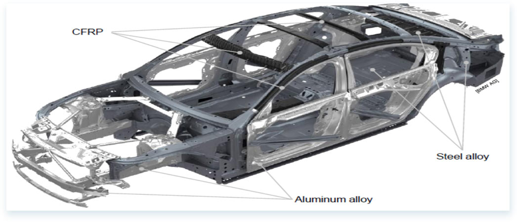
• Due to their superior mechanical properties, carbon fiber reinforced polymers (CFRP) are commonly used in lightweight applications, e.g. aviation or car industry. High structural performance to mass ratio, utilization of anisotropy for tailored strength, stiffness and stability design, excellent fatigue behavior and corrosion resistance are distinguished attributes of CFRP.
• However, their brittle failure behavior limits the structural integrity and damage tolerance in case of impact (e.g. tool drop, tire debris, hail strike) and crash events. Furthermore, the electrical conductivity of CFRP structures is insufficient for certain applications. A novel approach is the incorporation of highly conductive and ductile continuous metal fibers into CFRP.
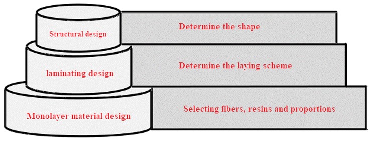
• We have a complete set of solutions to the difficulties of composite design, including how to design single-layer materials quickly, how to design rapid layers, how to quickly and efficiently identify the weaknesses of composite materials and a series of difficulties in composite material design.
• Taking the research of an automobile composite material as an example, the difficulties in the process of composite material design are introduced in detail. In this case, the microstructures and mechanical properties of CSFRP are analyzed by simulation calculation. Design ideas of CSFRP: (1) Determining material and structure of matrix and reinforcement ;(2) Modeling of composite materials, primary laying sequence; (3) Digital analysis of composite material model, including geometric analysis, mechanical analysis, flow simulation and conductivity analysis; (4) Adjust the design parameters by analyzing the results; (5) Testing and production.
1.Material Structure
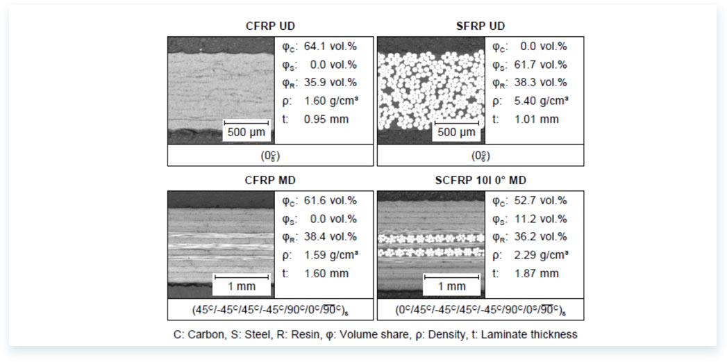
UD: Unidirectional
MD: Multi-directional
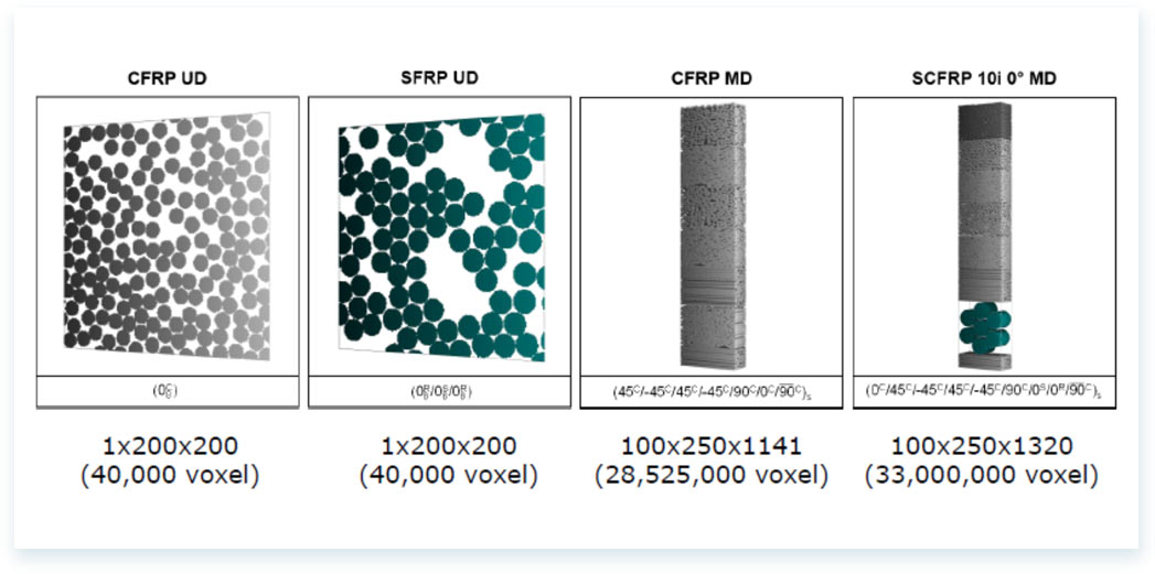
2.Modeling of Composite Materials
CFRP UD and SFRP UD have an element length of 0.5 μm and a size of 1x200x200 elements in x-y-z-direction.。
CFRP MD and SCFRP 10i 0°MD have an element length of 0.7 μm and the same element size.
3.SCFRP 10i 0°MD Mechanical Analysis
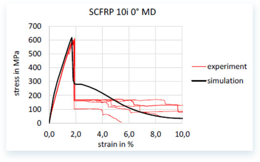
The simulation of the hybrid SCFRP 10i 0° MD material sets high demands on the software, because of the very different material properties and the different fiber diameter scales between the steel (60 μm) and the carbon fiber (7 μm). The simulation reproduces the material behavior quite good until the first ply-failure. The stiffness as well as the point of failure of the first ply is in good agreement with the experiments.
4.Visualization
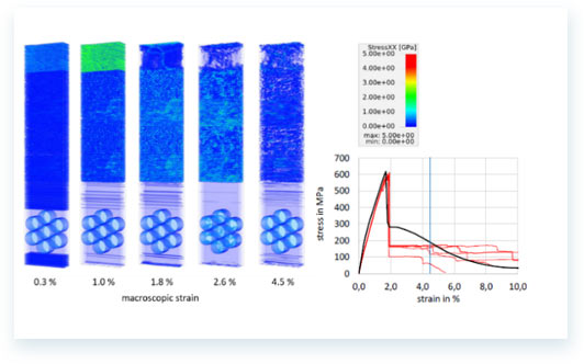
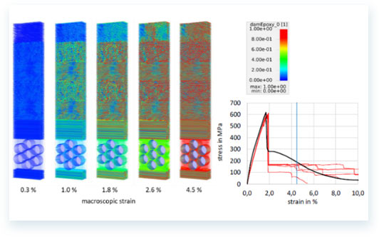
To understand the functionality and the micromechanical behavior of the material, the visualization of the simulation results for the different load steps is very useful. Figure 1 shows the stress in loading directions for different macroscopic strain-states. At 1 % strain, it is clearly visible that the upper 0°-ply carries most of the load. After the failure of this ply at 1.8 % strain, the stress inside the ply as well as the macroscopic stress drops significantly. Figure 2 shows a plot of the UMAT state variable of the damage parameter in the epoxy resin material model.Until the failure of the 0°-ply at 1.8 % strain, the matrix damage mainly occurs in the ±45°- and 90°-plies. After the breakage of the 0°-ply the matrix damage evolves in all plies until at 4.5 % almost the entire matrix is damaged.
